DC to DC converter steps up low DC voltage or steps down high DC voltage to a more acceptable voltages to be used on control boards and other low voltage devices.
When I started working on electronic circuits during my basic school level at Begoro Roman catholic School, my biggest problem was how to step down high voltages to applicable level for components operation.
Am therefore sharing this post so that many electronic hobbyists who are confronted with this same challenge even at their higher levels will be able to have their way through after reading this post.
DC TO DC CONVERTER STEP UP STEP DOWN (BOOST / BUCK) USING UC3845
Buck converter circuit is a DC to DC converter circuit that steps down a higher DC voltage to a lower DC voltage.
A boost converter on the other hand is a DC to DC converter circuit which produces a higher DC voltage from a lower DC voltage.
Both converters can only be achieved by using appropriate switching technique at a desired frequency. (20kHz. to 80kHz.)
UC3845 PWM DC TO DC CONVERTER IC
The UC3845 IC is a pulse width modulated IC with 50 percent duty cycle. The IC operates with a supply voltage of 8V to 32V DC but works best with 8V-14V.
The output frequency of the IC is calculated with this formula:
frequency (f)=1.8/(Rt x Ct). Download UC3845 datasheet from here.
STEP UP STEP DOWN DC TO DC CONVERTER CIRCUIT

DC TO DC CONVERTER Circuit operation
The circuit works with input voltage of 9V to 75V to produce either a stepped down DC voltage or Stepped up DC Voltage.
To set up the circuit:
- Set the operating voltage for the IC. The operating voltage is set by adjusting U3 until you get 10V to 14V on pin 7 or on capacitor C5. This should be done before inserting the IC.
- T1 is ferrite ring transformer with turns ratio of 1:1. The ring transformer is wound by winding the primary and the secondary at the same time as shown below.
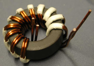
- though all ferrite rings will work, some works extremely well. That is iron powdered rings. they are mostly yellow.
TYPICAL WINDING TURNS FOR THE ABOVE DC TO DC CONVERTER CIRCUIT
12V input …………………….8 turns
24V input……………………. 16 turns
36V input…………………….. 24 turns
48V input……………………..32 turns
72V input………………………46 turns
NB: increase the number of turns if coil heats.
NB: Thick gauge means high current but do not use one thick coil, but use many smaller ones put together to avoid skin effect at high frequency. 18 gauge or smaller is OK.
- The operating frequency is determined by U1 and R3.
- D1 is any fast switching diode which can handle your desired output current.
- C2 is the output filter capacitor. it can be increased when handling higher output current.
- U2 is 10k variable resistor which is used for setting output voltage level. Never power the circuit without the feedback connected. Doing that will produce very high output voltage.
- R10 is a current sense resistor which provides short circuit and over current protection for the circuit. It can be reduced if higher output current is required.
